Etched Implants: A Comparative Surface Analysis of Four Implant Systems
Link: 
2003 Wiley Periodicals, Inc. J Biomed Mater Res Part B: Appl Biomater 69B: 46 –57, 2004
S. Szmukler-Moncler,1,2 T. Testori,2 J. P. Bernard1
1 Department of Oral Surgery, School of Dental Medicine, University of Geneva, Barthe´ le´ my Menn 4, CH-1211 Geneva, Switzerland
2 Department of Odontology, Section of Implantology and Oral Rehabilitation, Galeazzi Orthopeadic Institut, University of Milano, Milano, Italy
Abstract: Surface texturing by acid etching has recently become popular among dental implant manufacturers. The aim of this study was to compare the surface topography of four implant systems and to check the reproducibility of the industrial process of each implant system. Three implants per system have been selected from three distinct batches. They were observed under a scanning electron microscope (SEM), and roughness was determined with a contact profilometer by measuring five height-descriptive parameters (Ra, Rq, RzISO, Rt, and Rsk, a texture parameter Sm, and a hybrid parameter R^q. The analysis showed that each implant system displayed a distinct surface topography that could not be mistaken. When sandblasting was performed prior to etching, surface topography was a combination of macroand microroughness. The roughness and the amount of remaining sand varied among the batches, showing that the industrial process is not fully developed. Deviation from the released technical information was found for two out of four implant manufacturers. Based on the available biological and clinical data on textured surfaces, it is suggested that it is bone interlocking at the interface that maintains the biological properties of textured surfaces, rather than a strong implant fixation per se.
Keywords: acid etching; Osseotite; sandblasting; SLA; surface treatment
Obs: SLA-ITI: A large amount of alumina particles remained from the roughening process, indicated as white spots [Figure 3.a-c]. Two different patterns were observed, since some areas were not sand-blasted (Figure 3.d), but rather machined and etched. The 10-mm-long implant seems smoother than the 8-mm-long implant, and the 12-mm-long implant seems to be the smoothest of all three (Figure 3.e-g). The rougher the surface was, the more contamination by alumina particles was observed. Deep pits, created by the etching process, which encourage bone growth, are visible (Figure 3.i-j). The surface displayed micro-and-macro roughness; however, it was not replicable.
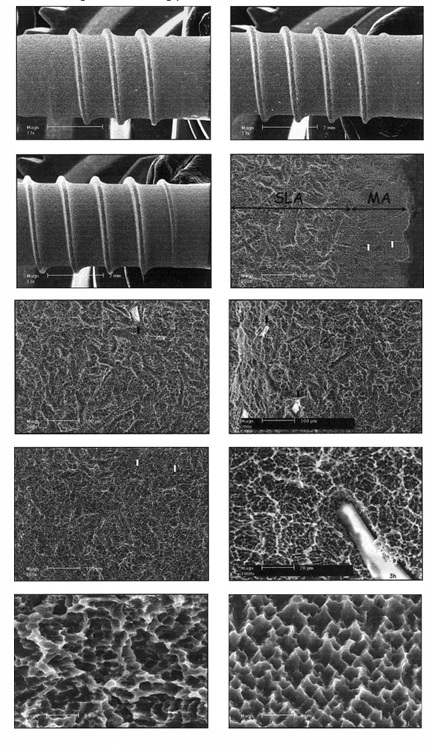
Figure 3: SEM micrographs of the surface of the SLA-ITI 8-mm-long (a), 10-mm-long (b) and 12-mm-long (c) implants. White spots indicate alumina particles. Area (d) is the transitional area between the neck and SLA surface of the implant. White arrows point to where the grain boundaries of the metal were exposed. Macroroughness of the 8-mm-long (e), 10-mm-long (f) and 12-mm-long (g) implants. Area (h) is a high-magnification view of the macro-and-microroughness. Microroughness of the SLA
Obs: Note: Please look at the white dots that are aluminum oxide, just like the analysis we presented at the Implante Institute.